
Motorized tracking and following a mouse
This project is in collaboration with the Shepherd Lab at the Feinberg School of Medicine. The goal is to study the multi-motor and sensorimotor coordination in mice feeding behavior. Previous setups aimed at examining this held the mice stationary while recording feeding footage from below them.
This new setup was developed in order to capture this camera footage while allowing the mice to roam freely. Two stepper motors are used along with a trained network (using DeepLabCut) to move and keep the camera under the mouse at all times.
Video Demo
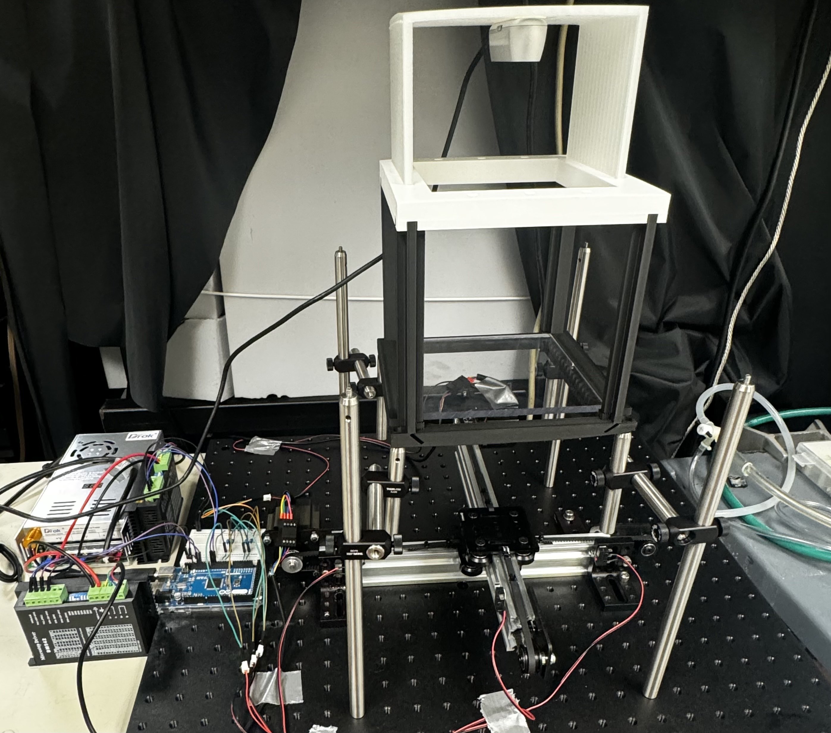
System Overview

Mechatronics

Two Nema 23 bipolar stepper motors are mounted perpendicularly onto linear actuator belts for controlling the motion of the bottom camera. They are driven by two-phase DM542 microstepping drivers and powered by a 48V, 10A ACDC converter.
For calibrating the stepper motor range, limit switches are placed at the ends of each belt. The motors move towards one switch per axis to zero out. After calibration, the system switches to a tracking state where it will move to given goal positions coming in over a serial port. This is done with open-loop controller configured with the AccelStepper library that can be interrupted when new goal positions are parsed.
As a safety mechanism, the signal from the normally open switches are attached to interrupt service routines. If an interrupt is generated in the tracking state, the motor rapidly accelerates in the other direction to prevent any collision. The system then begins calibrating again. The Arduino’s internal pull-up resistors ensure that the normally open switches are in a high state (rather than floating). When the signal is pulled to low, interrupts are triggered. Capacitors are also connected in parallel with the switches to debounce and act as low pass filters.
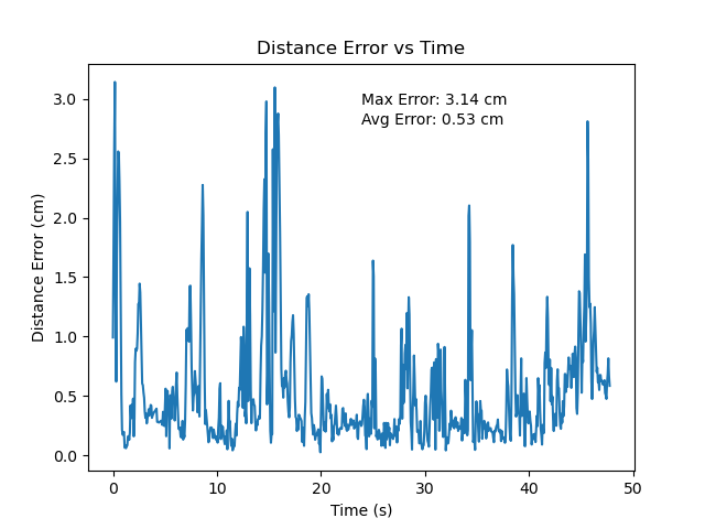
The DM542 drivers have 8 toggleable bits to configure its RMS, peak, and standstill current as well as its level of microstepping. To assess performance with different levels of microstepping, a benchmarking tool was developed. A fiducial marker is attached to the load, enabling error metrics (the distance between the desired and current position) to be measured. Speeds and accelerations were maximized up until the motors started missing steps.
| Microstepping Resolution | Average Error (cm) with Moving Average Filter (window_size=3) |
|---|---|
| 1/8 | 0.72 |
| 1/16 | 0.65 |
| 1/32 | 0.53 |
| 1/64 | 0.57 |
| 1/128 | 0.59 |
Computer Vision
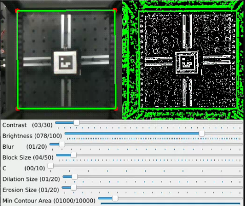
The previous iteration of this project had corners of the mouse workspace as tracked features; this was deemed unnecessarily taxing on the inference speed of the live model. To replace it, a corner detector using OpenCV was added. The steps can be summarized as follows:
- Image capture
- Contrast and brightness adjustment
- Median blurring
- Adaptive thresholding
- Morphological operations (dilation followed by erosion)
- Contour detection
- Polygon approximation on the largest contour
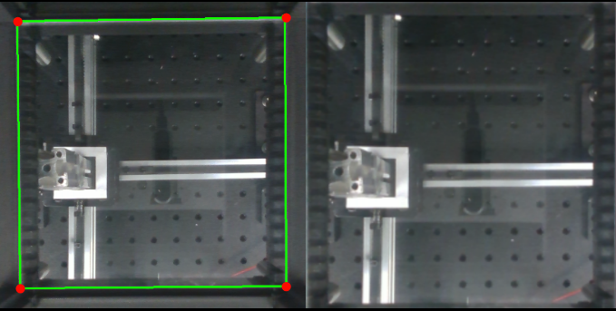
The detected corners are then used to estimate the homography between the camera image plane and cage plane. This is used for perspective correction, since it is known that the corners should form a non-slanted square:
Deep Learning
All models used for mouse feature prediction were trained using DeepLabCut.. Since this is a live setup, achieving high inference speed was crucial. To optimize performance, different pre-trained network architectures were tested for the purposes of tracking the ears of mice.
The previous setup used a Jetson Nano with a 128-core Maxwell architecture. This was able to achieve an inference speed of ~16 fps at best. The benchmarking done below shows that this was a significant bottleneck, as the inference speed could increase by 8x with the higher end GPUs. This would also suggest that obtaining a camera with a higher framerate would enable faster tracking.
| Model | Engine | # Params | Training loss (last iter) | Testing RMSE (pixels) | Inference Speed (FPS) RTX 4060 | Inference Speed (FPS) RTX 6000 |
|---|---|---|---|---|---|---|
| mobilenet_v2_1.0 | TensorFlow | 2,327,207 | 0.0018 | 2.05 | 125.44 | 332.29 |
| mobilenet_v2_0.75 | TensorFlow | 1,451,287 | 0.0019 | 2.16 | 154.30 | 334.08 |
| mobilenet_v2_0.50 | TensorFlow | 775,447 | 0.0022 | 2.48 | 182.60 | 324.2 |
| mobilenet_v2_0.35 | TensorFlow | 479,431 | 0.0024 | 3.04 | 192.11 | 327.71 |
| efficientnet-b0 | TensorFlow | 3,652,310 | 0.0018 | 1.99 | 138.75 | 283.48 |
| efficientnet-b3 | TensorFlow | 10,208,531 | 0.0024 | 2.05 | 86.86 | 243.18 |
| resnet_50 | PyTorch | 23,618,630 | 0.00009 | 1.5 | N/A | N/A |
| resnet_50 | TensorFlow | 23,672,033 | 0.0016 | 2.11 | N/A | N/A |
| resnet_101 | TensorFlow | 42,716,385 | 0.0015 | 1.91 | N/A | N/A |
| mobilenet_v2_1.0 | PyTorch | 1,401,903 | 0.0011 | 1.9 | N/A | N/A |
Collaborators
Thanks to Matt Elwin, Mang Gao, John Barrett, Gordon Shepherd, for guidance and collaboration.
Check out the project → GitHub